Settings > Sensor > System Settings
This page provides general settings for your COMMANDassurance or TrackIt Delivery Cycle Monitoring systems.
TrackIt Delivery Cycle Monitoring
The below units and measurements are used by the Sensor Link display and by the LoadThe total amount of concrete or asphalt that is being or has been batched for delivery. Properties card to properly calculate and display readings retrieved from the Drum Rotation Sensor.
COMMANDassurance
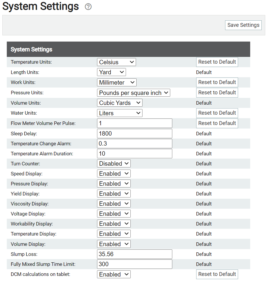
The COMMANDassurance ProbeA probe device mounted in the side of a bin to measure the moisture content of aggregate materials such as sand. is equipped with a visual display, the Sensor Link, on the side of a vehicle that displays the various properties of a drum's loadThe total amount of concrete or asphalt that is being or has been batched for delivery.. The information displayed, its precision measurements, and the metrics used are controlled from this screen.
|
Measuring the temperature of a load helps to ensure the integrity of concrete mixture. This setting controls how temperatures are shown on the Load Properties card, namely in units of Fahrenheit or Celsius. |
|
|
The total circumference of a vehicle's drum helps in calculating the total load quantity possible. This setting controls how the drum size is measured, such as Meters or Yard.
|
|
|
The workabilityThe consistency of fresh concrete before it sets is called workability. The makeup of a mix is measured using a slump flow test to measure both vertical and horizontal settling. Slump factors in the viscous nature of a mixture and is measured vertically. Spread factors in the flow of the material and is measured horizontally. of fresh concrete mixtures, meaning the ease of placement and compacting, is measured based on the size of casting work commonly done. This setting controls how a load's workability is shown on the Load Properties card, namely in units of Millimeter, Centimeter, and Inch. |
|
|
The precision of workability readings from the probe may be set to round up decimal levels for ease of reading. The value entered here indicates what increment is used for rounding load property readings. |
|
|
The precision of a new load's initial volume readings from the probe may be set to round up decimal levels for ease of reading. This precision metric is rounded differently from conventional rounding. The probe measures volume at different angles in the drum to estimate concrete height. This is then used to determine the measured volume of concrete in the drum. The volume is best measured when the drum speed is set between +0.5 and +3 RPM (low speed range). |
|
|
The precision of a load's current volume when unloading at a jobA project that orders and tickets are grouped under. site may be set to round up decimal levels for ease of reading. The value entered here indicates what increment is used for rounding load property readings. |
|
|
The unit of measurement used by the probe to correlate with workability of a concrete mixture. This is measured by pounds per square inch (PSI) or kilopascal (kPa).
|
|
|
The unit of measurement used by the probe to indicate drum volume, as shown on the Load Properties card. This may be set to Cubic Yards or Cubic Meters. |
|
|
The unit of measurement used by the probe to indicate quantities of water added to a concrete mixture for trimAny water added in the drum that is not measured by the batching system, PLPM, or the water flow meter installed on the truck. At this point, it is safe to assume that any water added at the slump stand is rogue water. purposes. This may be set to Gallons, Liters, Cubic Yards, or Cubic Meters. |
|
|
The total amount of water volume per pulse on a calibrated flow meter. The unit of measurement is based on the Water Units setting. |
|
|
When the drum is not rotating, it defaults to sleep mode once time specified here (in seconds) is elapsed. The probe regularly checks its position and wakes up if the drum has moved significantly from its last position reported. |
|
|
When a temperature change exceeds this value in a four-second time lapse, an alarm will trigger. If temperature changes this much in a 4 seconds time lapse, the alarm will trigger. The temperature display blinks while alarm is in effect. Specify the number of degrees that will trigger a temperature alarm if an increase happens within a four-second interval. The temperature display blinks while the alarm is in effect. |
|
|
The total duration in minutes that a temperature alarm should last on the probe display. Once the time elapses, then the temperature ceases to flash. |
|
|
The drum's turn count is tallied on the probe receiver display. This will replace the Voltage Display value if enabled. If this is enabled, the voltage display will show the turn count instead of the battery voltage Select enable to show the turn count of drum instead of the voltage on the voltage display |
|
|
The current detected drum rotation speed is shown on the probe receiver display. |
|
|
The pressure of the concrete mixture measured by the drum probe is shown on the probe receiver display. The pressure measured in the last drum rotation will appear solid, whereas the immediate pressure will blink on the display. Pressure is measured by the position (angle), speed, and direction of the drum in addition to the level of concrete in the drum. |
|
|
The yield of the concrete mixture measured by the drum probe is shown on the probe receiver display. |
|
|
The viscosityA concrete's resistance to flow under external stress. measured by the drum probe is shown on the probe receiver display. |
|
|
The voltage of the probe's solor panel is shown on the probe receiver display. The Turn Counter value may display here instead if the option is set to Disabled. |
|
|
The concrete mixture workability measured in the drum is displayed on the probe receiver display. |
|
|
The measured temperature of the concrete mixture in the drum is shown on the probe receiver display. |
|
|
The concrete volume measured in the drum is shown on the probe receiver display. Calculated values are shown as a solid number, whereas measured volume will force the display to blink. |
Configuring precision parameters
Precision parameters control how values are rounded before being displayed. This is done to improve the ease of quantifying a load and reducing decimal values. Users most often choose to round values to the nearest increment of 0.1, 0.25, and 0.5. The final value of a load's volume based on these metrics are constrained by the following rules:
- Values cannot exceed 3 digits. If a rounded value is greater than this, it is rounded up once more to the nearest tenth. For example, 10.25 is rounded again to 10.3.
- Values are rounded up when they exceed 50% of the precision parameter set. This threshold is different for the Initial Volume Precision field.
For example, if your precision parameter is set to 0.25, the probe's display panel would display the values shown below.
| Precision=0.25, Threshold=50% | |
|---|---|
| Actual Value | Displayed Value |
| 10.121234 | 10 |
| 10.138673 | 10.25 (10.3 since only 3 digits) |
| 10.381546 | 10.5 |
Initial Volume Precision rounding
With the Initial Volume Precision field, the rounding formula is different from standard 50% threshold. Values here are rounded up when a threshold of 20% or more (versus the standard 50%) of the specified precision value is reached.
For example, if your precision parameter is set to 0.25, the probe's display panel would display the values shown below.
| Precision=0.5, Threshold=20% | |
|---|---|
| Actual Value | Displayed Value |
| 7.09 | 7 |
| 7.1 | 7.5 |
| 7.5 | 7.5 |
| 7.59 | 7.5 |
| 7.6 | 8 |