| Overview |
|
Requirements |
|
Install Sensor Link |
|
Install DRS |
|
Install flowmeter |
|
Troubleshoot |
|---|---|---|---|---|---|---|---|---|---|---|

|
|
|
|
Installation of the Drum Rotation Sensor consists of two components: the sensor magnets and the sensor itself. One is installed on the drum, whereas the other is attached to the hydrostatic transmission case. The process of installing these components is quite straightforward and described further below.
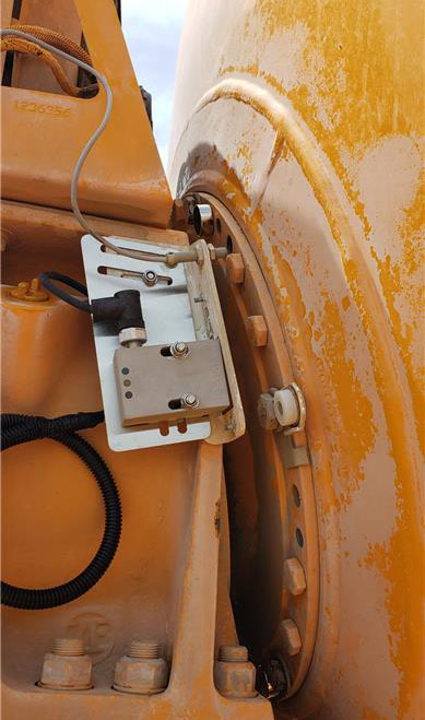
Installing the magnets
Typically, four (4) magnets are installed with even spacing around the flange. These are often done between existing bolts on the flat flange surface as shown above.
Three types of magnets may be used with the Novotron sensors.
- Bolts: Three (3) magnets instead of the typical four (4)
- Existing: Include different mounts
- Disc magnets: Four (4) magnets
Magnets are provided to signal speed and direction of the drum. As these magnets pass in proximity to the sensor, the sensor is able to determine rotation and speed. These magnets should be installed evenly around the flange of the hydrostatic transmission for the drum.
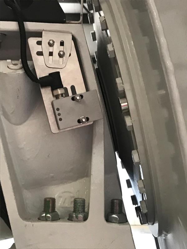
Installing the sensor bracket
Once the magnets are installed, you should now install the drum rotation sensor.
- Remove the bolt from the transmission case.
- Install the bracket below the case.
- Reinstall the existing washer and hex nut to attach bracket to case, leaving loose enough to adjust the sensor's position.
- Slide the upper bracket in or out to position the center of the magnetic sensor in line with the magnet path.
- Re-tighten the large nut to hold the bracket in position.
- If needed, loosen the small hardware to adjust the lower bracket so the long edge is parallel to the drum.
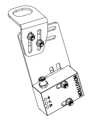
Bolt Magnet installation with pencil sensor
Attaching sensor to bracket
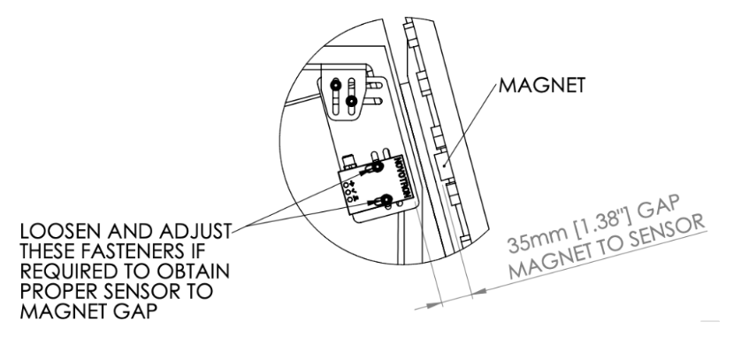
Spacing the sensor from the magnets
It is important that the spacing between the sensor and the magnets be set correctly. If the sensor is positioned too far away from the magnets, it may not pick up the magnets. Position the sensor too close and contact may occur between the sensor and magnets under extreme conditions.
The table below outlines the ideal proximity between the sensor and magnets.
| Bolt Magnets | Disc Magnets | |
|---|---|---|
| Compatible Sensor | Novotron V2 | Novotron V1 |
| Ideal Space | 1" (25mm) | 1-3/8" (35mm) |
| Minimum Space | 5/8" (15mm) | 7/8" (20mm) |
| Maximum Space | 1 3/8" (35mm) | 1-9/16" (40mm) |
Ensuring power to the sensor
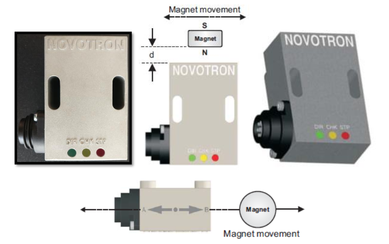
After connecting the Drum Rotation Sensor and cabling, make sure it is powered by turning on the truckAll machines used as a means of production on a construction site or at a batch plant. ignition. You may then confirm functionality of the sensor using the magnet and the three LED’s on the sensor as follows:
- One side of the sensor is marked by an arrow and the letters A and B. When moving a magnet along the arrow, the sensor will detect the magnet moving direction and switch the output relay DIR accordingly. The green LED DIR (direction) will indicate the current output state.
- Each time the magnet passes, the output relay STP (stop) provides a one-second pulse.
- If the magnet passes close enough to the sensor close to generate a safe signal amplitude, the yellow CHK (check) will be switched on for one second.
Make sure that the magnet’s center moves aligned with the arrow marking on one side of the sensor, and that the CHK LED switches on when the magnet passes.
|
|
|