| Overview |
|
Requirements |
|
Cables |
|
Installation |
|
Configuration |
|---|---|---|---|---|---|---|---|---|

|
|
|
|
The process of integrating the EDC into your vehicleAll machines used as a means of production on a construction site or at a batch plant. equipmentAll machines used as a means of production on a construction site or at a batch plant. entails three steps:
- Remove the previous OBC hardware
- Attach the EDC to the diagnostic cable
- Install the power and engine diagnostic cable
Removing the previous OBC hardware
If you're upgrading from a previous TrackIt system, then the OBC components such as those shown below are no longed needed and may be removed from the vehicle.
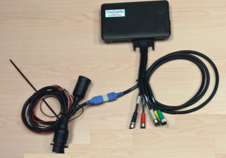
You can likewise disassemble components on the truckAll machines used as a means of production on a construction site or at a batch plant. associated with the system, such as:
- Existing GPS and cellular data antennae such as pucks, whips, and fins
- OBC mounting hardware
If you presently use tablets with cellular plans, you may continue to use them with the EDC. However, your cellular plan must include mobile hotspotGeographic areas marked on a map that act as destinations for driver navigation or triggers for automated behaviors in TrackIt. functionality.
Attaching the EDC to the diagnostic cable
Connecting the EDC with the included power and diagnostic cable entails only mating the connectors and fastening the connection.
Prior to installing the diagnostic and power cable in your vehiclesAll machines used as a means of production on a construction site or at a batch plant., connect the EDC to the cable. This process is illustrated below.
|
|
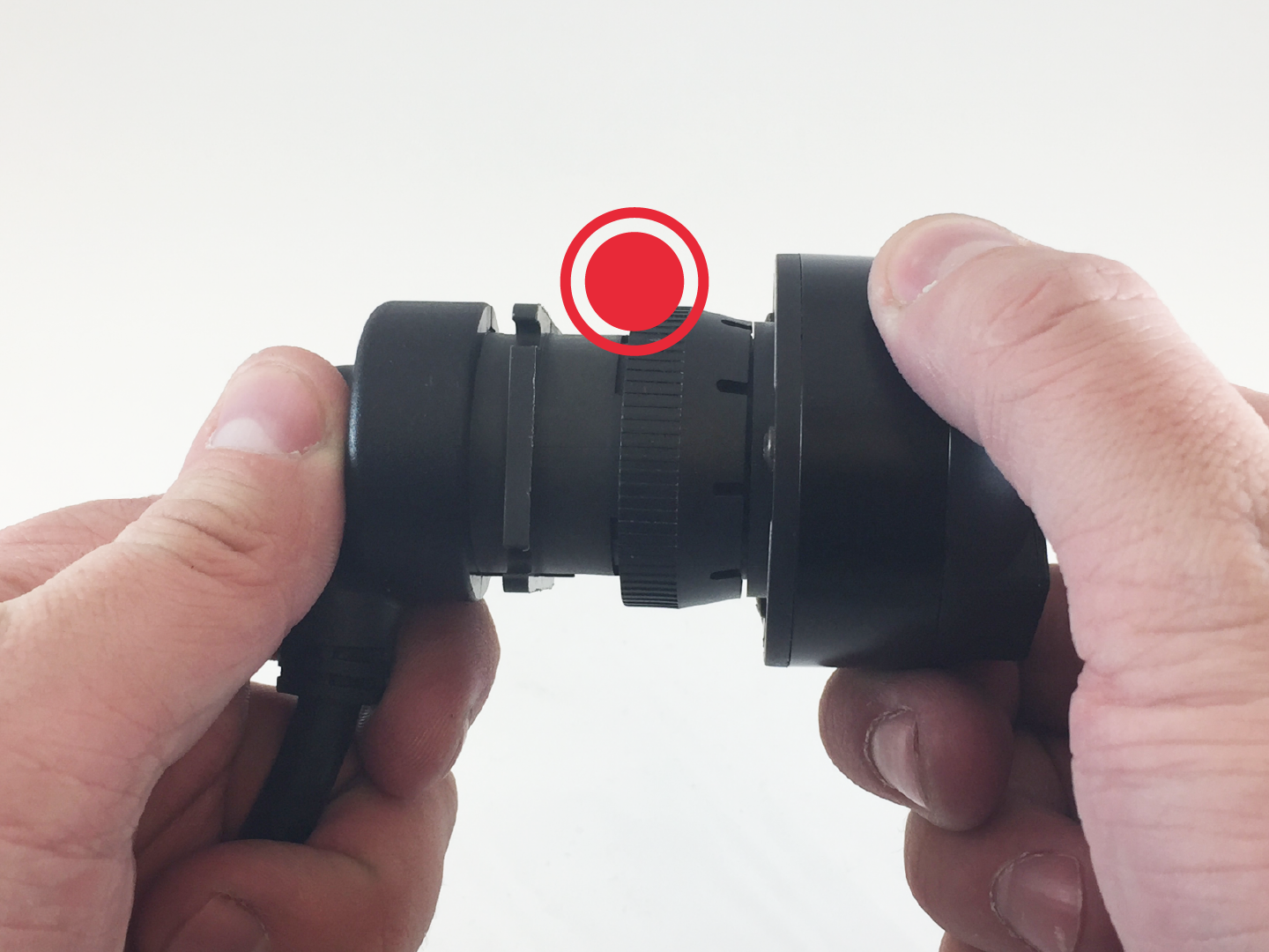
Step 1
Attach the EDC to the "tail" of the cable. |
|
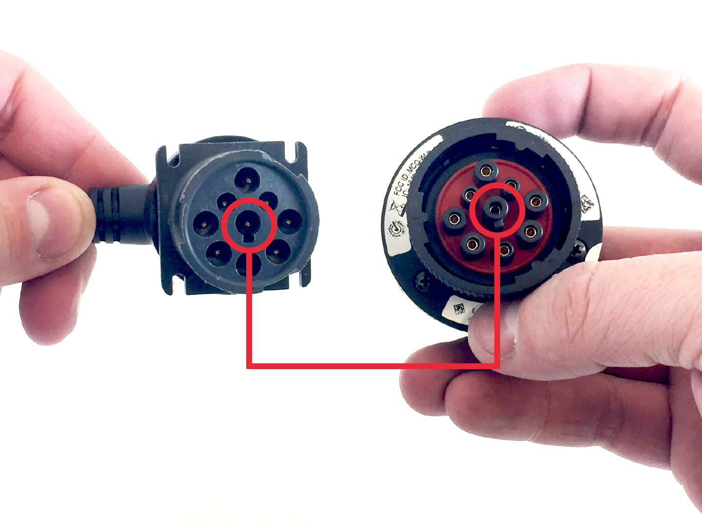
Step 2
Align the central connector pins. |
|
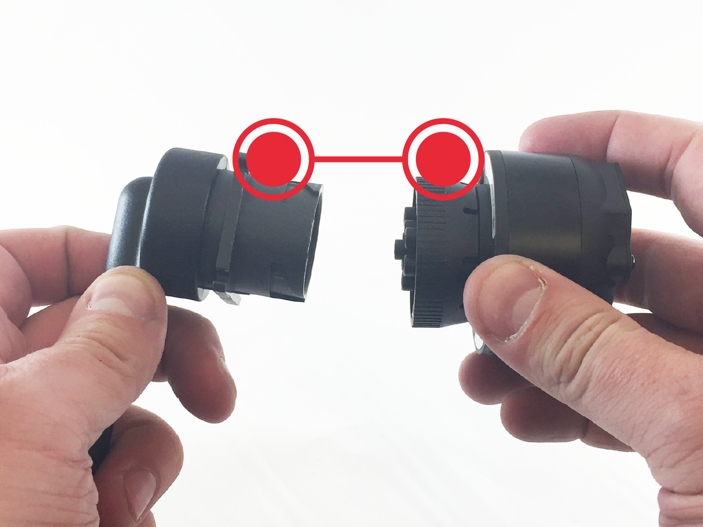
Step 3
Mate the connectors. |
|
|
|
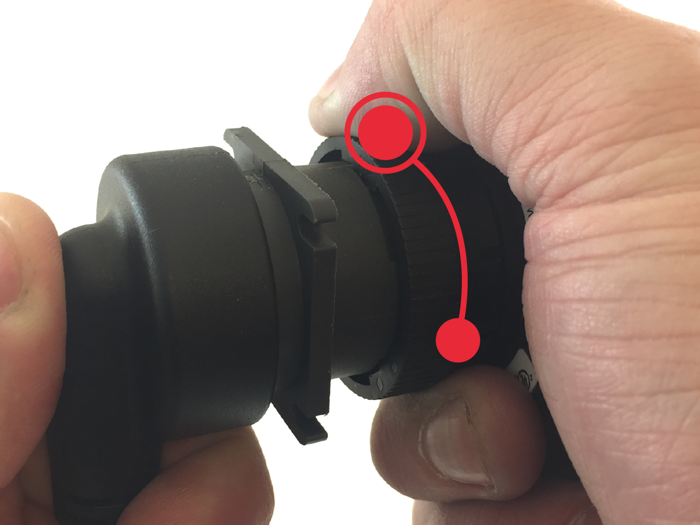
Step 4
Mate the connectors. |
|
Step 5
Secure the connection by twisting the fastener counter-clockwise. |
|
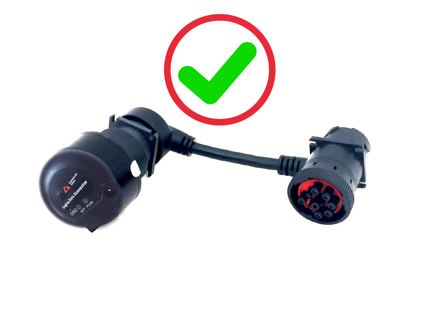
Step 6
The cable and EDC are ready for installation. |
|
Installing the power & engine diagnostic cable
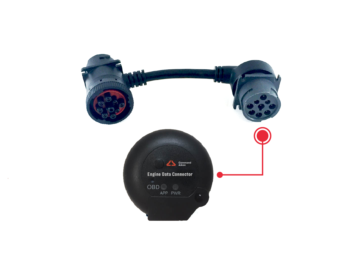
The cable included with the system uses a splitter design consisting of at least one Deutsch 9-pin port for the EDC itself and then two ports for the Engine Control Unit (ECUAlso known as an engine control module, this device controls engine performance by monitoring data reported by myriad built-in sensors. This data is interpreted by the ECU and then relayed to engine diagnostic hardware, such as an OBC or EDC.) and diagnostic connections. The type of cable included with your EDC is based upon the configuration you selected when purchasing equipment.
As an example, the basic Deutsch Type 1 cable is shown in the diagram below and identifies which connector should be used for each vehicle component.
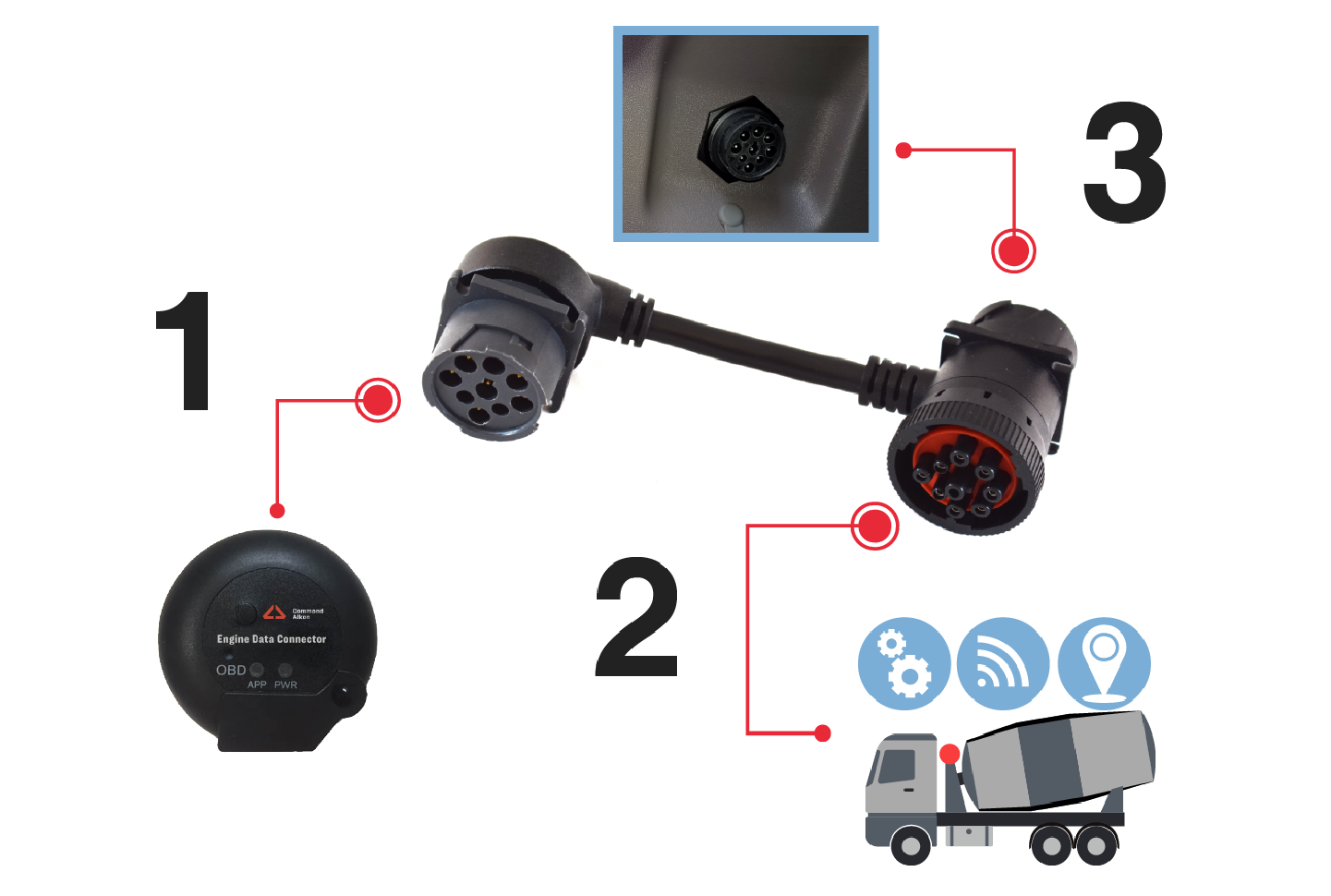
- Command Alkon Incorporated Engine Data Controller (EDC)
- Vehicle ECU
- Diagnostic equipment
- Remove the existing diagnostic cable from the vehicle.
- Identify each connector of your new power/engine diagnostic cable as shown above and match them to your existing vehicle connection points.
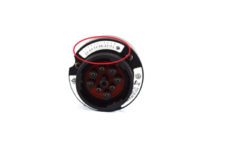
Write down the EDC's MAC address to use for the configuration step. Verify that the MAC address on the QR code sticker included within the EDC packaging.
- Connect the EDC to the connector along the "tail" of the cable.
- Mate and fasten the female connector on the splitter head with the ECU connector in the vehicle.
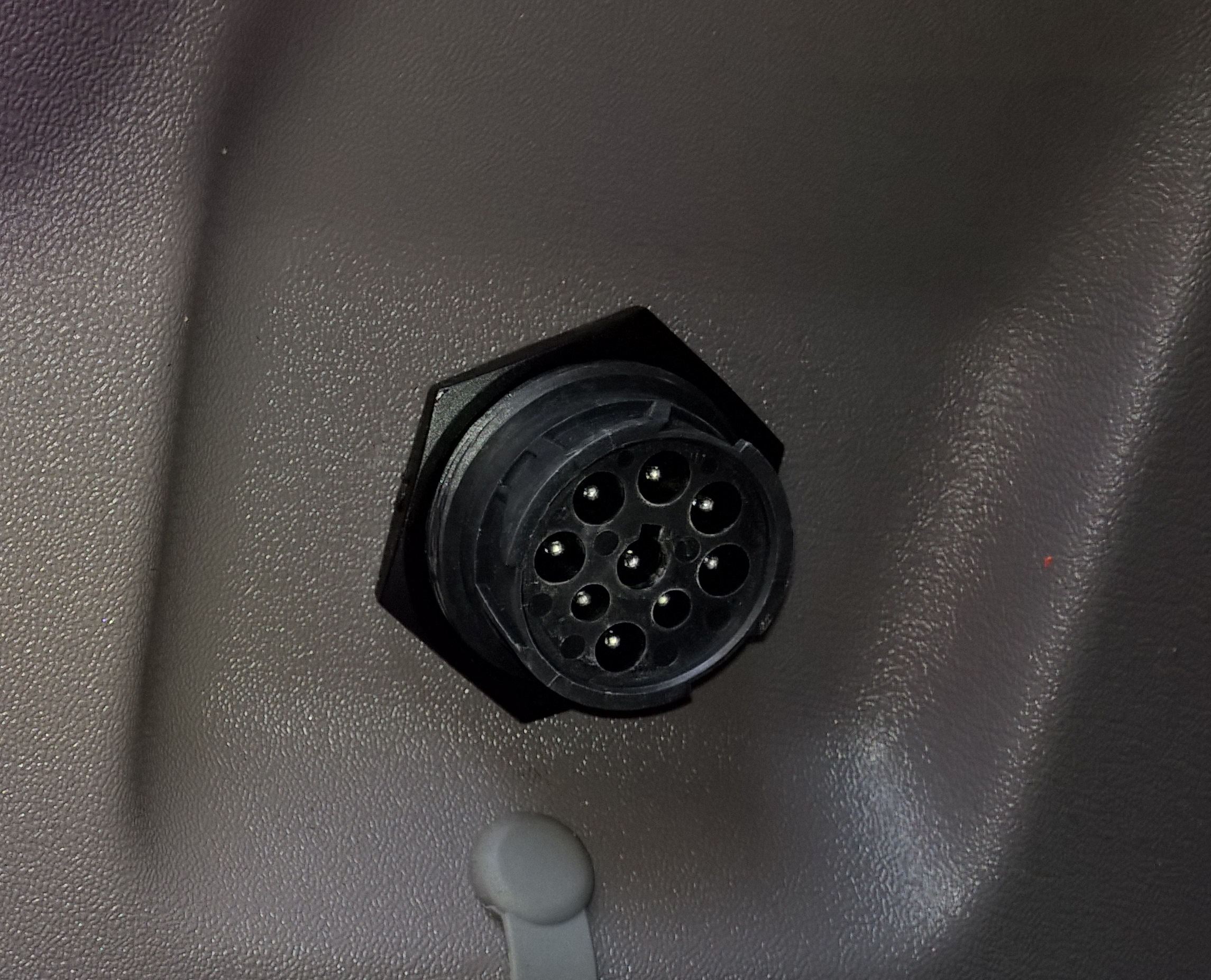
- Ensure that the connector opposite to the ECU connector is accessible to diagnostic equipment, as shown in the example below. Using a threaded fastener or flanged mount, you can secure the connector to the vehicle cab wall.
|
|
|