| Overview |
|
Requirements |
|
Installing display |
|
Installing probe |
|
Installing flowmeter |
|
Installing OBC/EDC |
|
Connecting cables |
|
FAQ |
|---|---|---|---|---|---|---|---|---|---|---|---|---|---|---|

|
|
|
|
The Installation process is a series of simple operations:
- Selecting the location of the probe.
- Installing the support plate.
- Installing the probe, control unit, and solar panel
Select and mark the installation location
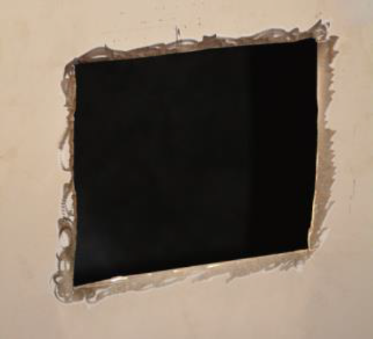
Cut the drum
Grind the interior of the cut
Weld the support plate
Insert the rubber gasket and the sensor
Fix both control-unit pieces
Fix the cables inside the control-unit
Selecting the location of the probe
Selecting the probeA probe device mounted in the side of a bin to measure the moisture content of aggregate materials such as sand. location is a very important step as you must consider the following:
- The gap between the drum and the frame should be suitable for the probe recess
- The probe must not be submerged in concrete when at top position
- The probe should not be positioned too far at the back of the truckAll machines used as a means of production on a construction site or at a batch plant. to ensure proper self-cleaning
- The probe should not be too close to the internal blades
The probe should be location as much as possible to the front, while also allowing the probe to clear the concrete when at the highest point during a drum revolution.
By placing the probe toward the front of the drum, this will ease its cleaning and help it to accurately measure concrete characteristics with a small concrete loadThe total amount of concrete or asphalt that is being or has been batched for delivery.. At the lowest point during a revolution, the probe must be fully immersed in concrete to give accurate results, as shown in the images below.

|

|
When the probe is too close to the blades inside the drum, the workabilityThe consistency of fresh concrete before it sets is called workability. The makeup of a mix is measured using a slump flow test to measure both vertical and horizontal settling. Slump factors in the viscous nature of a mixture and is measured vertically. Spread factors in the flow of the material and is measured horizontally. measurement may be affected and the slumpSlump is defined as the number of inches (or millimeters) concrete will sag, or slump, when a special test cone filled with the concrete is turned upside down and the cone pulled off the concrete. In other markets this is called ‘consistency’. Consistency for concrete can be stated different ways. Examples are: slump, flow, workability. We mostly use ‘slump’. (or spreadThe consistency of fresh concrete before it sets is called workability. The makeup of a mix is measured using a slump flow test to measure both vertical and horizontal settling. Slump factors in the viscous nature of a mixture and is measured vertically. Spread factors in the flow of the material and is measured horizontally.) might be higher than the slump obtained by manual slump test.

|

|
The best results are achieved when the probe is centered between two adjacent spiral blades.
The hatch, depending on its location on the drum, often represents a good place to install the probe mainly because this place is almost always exempt of any blade.
.")
Installing the support plate
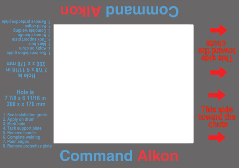
To get accurate readings, the probe should be aligned with both axes. Place the magnetic template parallel to the drum’s rotation axis welding lines with designated side toward the chute. Use it to mark the hole.
|

|
- Mark the location of the hole using the magnetic template.
- Cut the drum using appropriate tool (grinder, torch set, plasma cutter, etc.). Note the exact location for future installations on similar drum type.
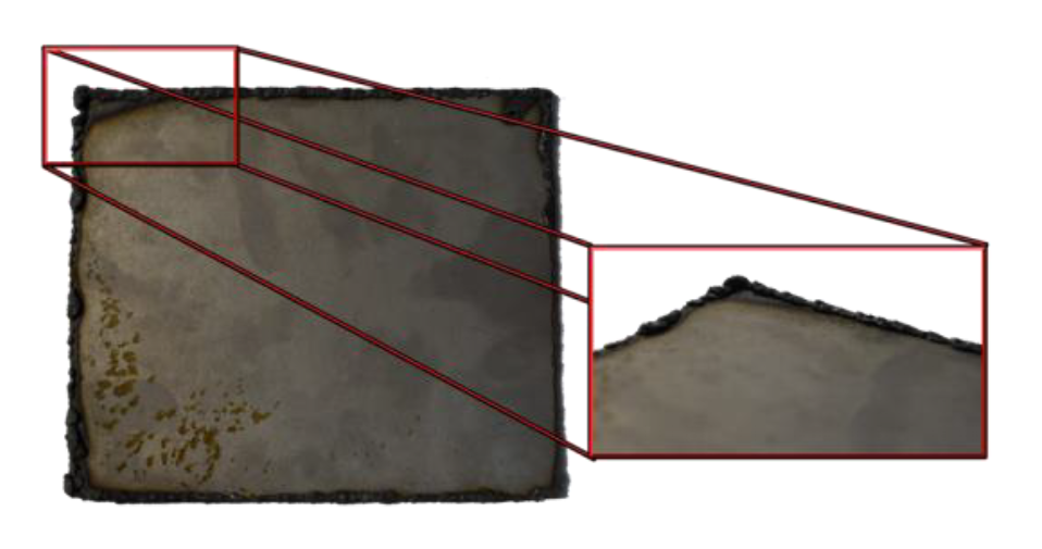
- Grind the residues excess on the inside of the drum to avoid creating a gap between the drum and the support plate. Make sure that the O-ring is not inside the plate before welding.
- Fix the handle and protecting plate on the internal plate and insert it inside the drum.
- Pull and align it on the rotation axis, and tack it to secure it. Then remove the handle.
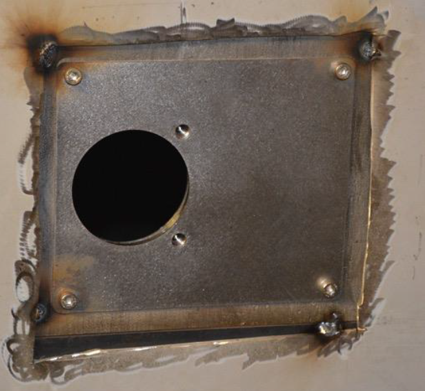
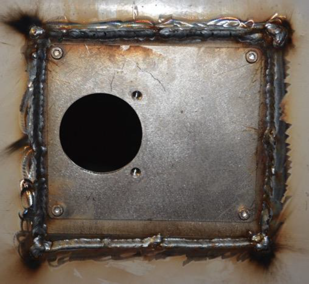
- Weld the plate all around its edges. Make sure to fill the left and right sides where the drum’s curve will cause a gap.
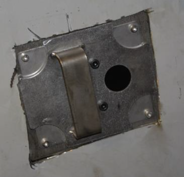
Installing the probe & control unit
The plate is now used to position the probe and its control unit. Once these components are installed, you'll then also install the solar panel to power the probe.
Note the Bluetooth ID (indicated by a sticker on the control unit) for ulterior registration of the system.
- Fix the first control unit part (right part) using screws M6 x 26 mm included in the kit. Insert the sensor into the hole of the support plate. Secure it using six M8 x 16 mm bolts (included in the kit).
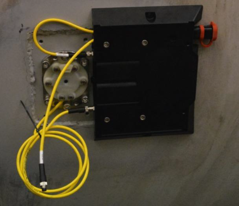
- Install and secure the second plastic part using M6 x 16 mm bolts as shown.
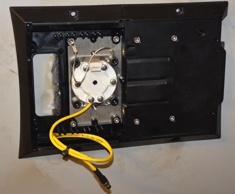
- Connect cable from the sensor to the control unit.
- Secure the sensor cable in the pins and clips. Plug it into the control unit.
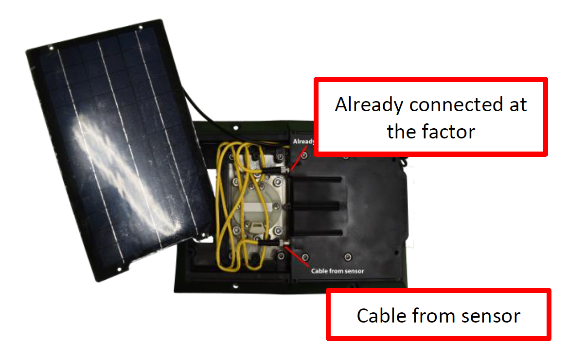
- Connect cable from the solar panel to the control unit.
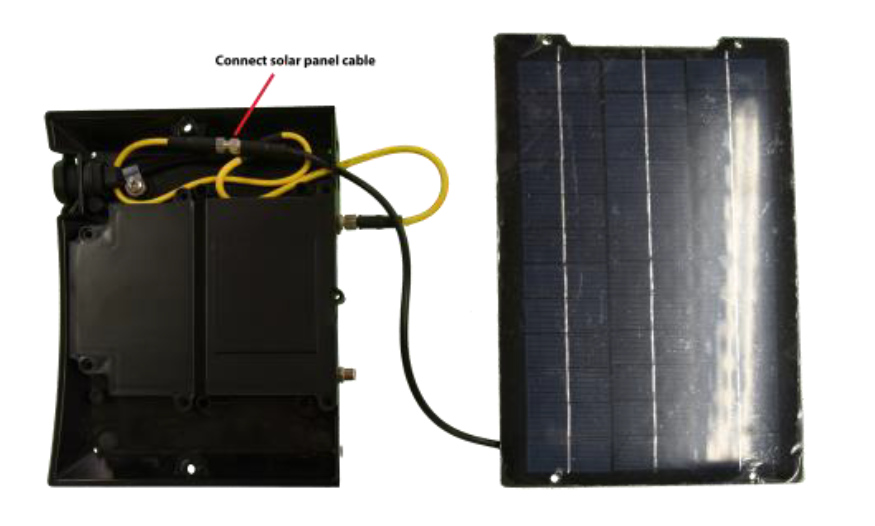
- Plug the solar panel in and secure the cable in the pins and clips.
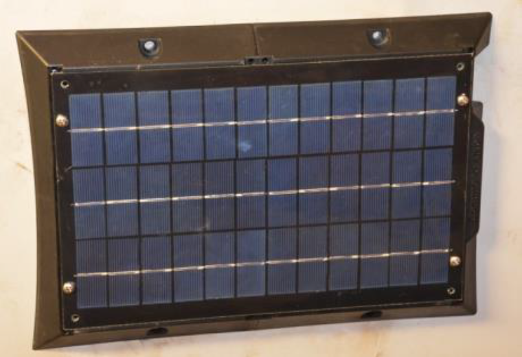
- Fix the solar panel using included screws.
|
|
|